
LTE-Advanced Carrier Aggregation : Definition, Advantages and CA Scenarios
The insistent demand for mobile data, particularly for streaming video, online gaming, and other data-intensive applications, are pushing mobile network operators to increase their capacity in terms of data throughput. Since the throughput is proportional to the bandwidth (wider is the band, faster is the data throughput), network providers need to offer high-bandwidth services in order to provide a good user experience. Thus how can network providers can achieve these goals with fragmented spectrum across multiple bands which width varies between regions?
One of the answers to this challenge is LTE-advanced carrier aggregation (CA). It has been defined for the first time in 3GPP release 10 [1]. The goal of carrier aggregation is to enhance network performance and ensure a high-quality user experience by enabling operators to provide higher uplink and downlink data rates using their existing spectrum. To do so, it combines multiple LTE system bands or carriers with different bandwidth (1.5 ; 3 ; 5 ; 10 ; 15 ; 20 MHz) across the available spectrum to support wider bandwidth signals, thus increasing the overall network throughput. Each aggregated carrier is referred to as a component carrier (CC) and the release 10 specifies that a maximum of five CC can be aggregated [2], hence a maximum aggregated bandwidth of 100 MHz.
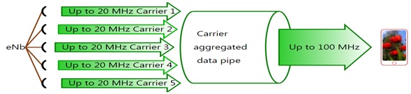
Carrier Aggregation combining 5 CCs to increase the overall bandwidth, thus data rates
There are three different carrier aggregation scenarios depending on the configurations of the Component Carriers: Intra-band contiguous carrier aggregation, uses multiple adjacent CCs within a single band while Intra-band non-contiguous carrier aggregation scenario aggregates carriers that are not adjacent within a single band. The third scenario, Inter-band non-contiguous, might be interesting for network operators due to the possibility of using fragmented frequency bands since it combines multiple CCs spread across multiple bands.
The three CA scenarios above are supported by Nutaq’s network in-a-box solution: the PicoLTE. More information about the PicoLTE can be found here.
As with other equipment available on the market, older versions (1st generation and version 1.1 of the second generation) of the PicoLTE were performing a software carrier aggregation by using only the LTE software stack and using the FPGA as a simple gateway to transmit and receive radio samples I and Q from and to the CPU. This underutilization of the FPGA increased the CPU load and quickly overloaded the capacity of the PCIe bus, link (connection) between the FPGA and the embedded PC.
For instance, in the case of CA inter band FDD with 2 Components Carriers : 2 DL non-contiguous of 5 MHz bandwidth spaced by 20 MHz, as shown in the figure below. In one direction, the PC would have received and processed the radio samples I and Q with(for) a total width of 30 MHz from the FPGA corresponding to the 2 carriers of 5 MHz and the spacing of 20 MHz.
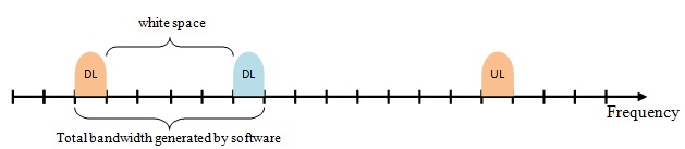
2 DL non-contiguous of 5 MHz bandwidth spaced by 20 MHz
In the other direction, the PC would have generated the data for the 2 carriers of 5 MHz width and fill the width of 20 MHz spacing between them before sending them to the FPGA via PCIe. This is equivalent to the throughput of 120 MBPS on the PCIe bus.
For the same scenario, with the new version of the PicoLTE, the PC only processes 40 MBPS of I and Q radio samples, corresponding to the two Components Carriers of 5 MHz each. This is because part of the processing previously carried out by the PC is now carried out in the FPGA. This reduces the CPU load and the amount of data transferred by the PCIe bus. In other words, the CPU performs less processing for the same over-the-air bandwidth.
Finally, the new version integrates the hardware very well with the software. Indeed, now the LTE software stack generates and processes only the interest bandwidth conveying the useful information. Then at the FPGA, these bands are shifted to the desired frequencies before being sent to the antennas. In this way, no spacing is taken into account in the PCIe throughput. This helps to increase the number of carriers components in carrier aggregation. The following two figures show the throughput test results without a) and with b) CA scenario of two 5MHz component carriers realize with Nutaq PicoLTE.
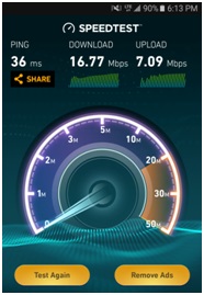
Speed test results of a single component carrier of 5MHz bandwidth

Speed test results with DL carrier aggregation of two CCs of 5MHz bandwidth each
It can be noted that the downlink throughput with CA illustrated in figure b) is practically twice that shown in figure b) without carrier aggregation.
The next blog will bring a step-by-step guide of PicoLTE configuration files implementing different carrier aggregation scenarios.
[1] Sassan Ahmadi, A pratical systems approach to understanding 3gpp lte release 10 and 11 radio access technologies Hardcover – Nov 14 2013[2] Carrier Aggregation for LTE v0.1.1 (2014-09) / www.3gpp.org – /ftp/Information/WORK_PLAN/Description_Releases/